
Gas Turbine Rotor.(HY industry- Technical Center internal data)
Request For Proposal
Contents
- Introduction
- Design Features
- Material Requirements
- Manufacturing Method
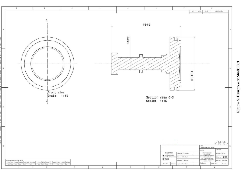
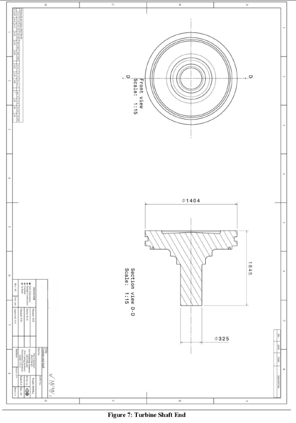
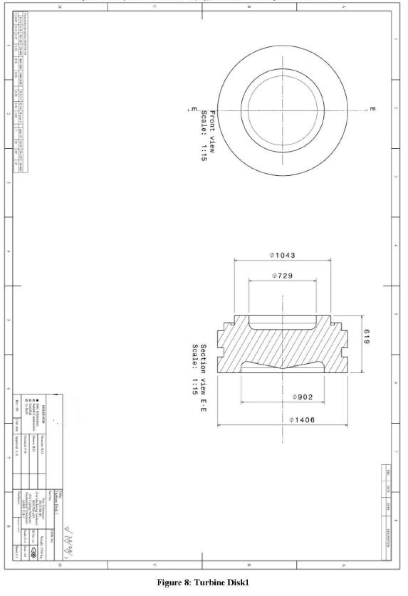
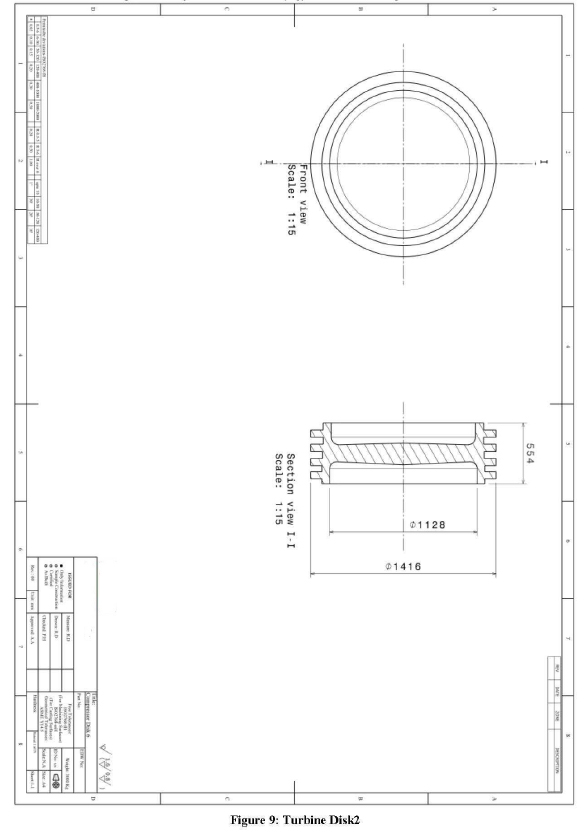
- Dimens1onsand Drawings
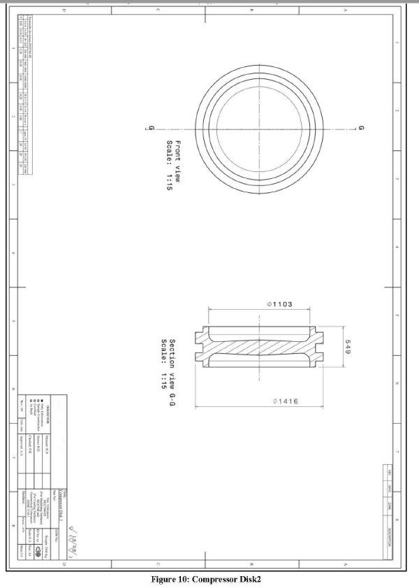
- Part Drawings
- Inspection and Reports
- Appendix!: Technical Delivery Specification for Forged Rotor Parts
- Appendix 2 : Rotor Pictures
Introduction
-
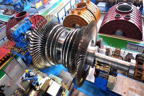
- This RFP includes some general information required for manufacturing of a 76 MW gas turbine rotor. This rotor is illustrated in picture below.
- The rotor blades are not the subject of this document.

Design Features
- Iso Base Load Rating: 76 MW Generator Set, Single Shaft
| Compressor | |
| Type: | Axial |
| No. Stages: | 17 |
| Desigt1 Speed : | 3000 rpm |
| Turbine | |
| Type: | Axial |
| No. Stages: | 5 |
| Design Speed: | 3000 rpm |
Material Requirements
Manufacturing Method :
Forging
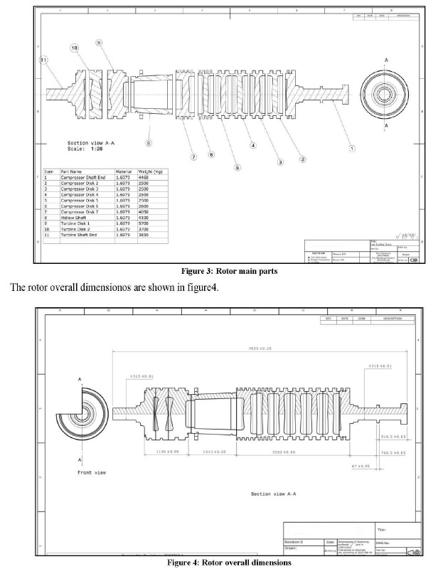
- The rotor main parts are manufactured by machining of forgings. These parts should be forged according to Appendix 1: Technical Delivery Specification for Forged Rotor Parts.
Welding
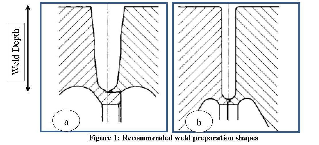
- The forged parts described in 3-1 shall be welded together to construct the rotor. Recommended joints for weld preparation are represented in figure1. Welding positions are represented in figure 2.
- Maximum welding depth is 200-250 mm.
- Appropriate heat treatment shall be applied on the rotor/welded areas.
- All welding areas should be inspected using Ultrasonic and Magnetic Particle method.
- Welding method and joint design, post welding heat treatment (PWHT) shall be cleared in the manufacturer proposal. WPS and PQR prepared for this rotor should be submitted to HY before starting the project.

Dimensions and Drawings
Inspection and Reports:
- The rotor parts shall be dimensionally checked and balanced individually before assembly.The heat stability test shall be performed on the rotor according to related standards. The test method and acceptance criteria shall be cleared in the proposal.The rotor assembly shall be dimensionally checked and high speed balanced after final machining and grinding.The standard and grade of balance shall be cleared in the manufacturer proposal.The rotor critical speed of the manufactured rotor shall be determined by the manufacturer.
Gas Turbine Rotor RFP
| Document Code | Revision | Date | ISO Code | Page | |
| PENG-RFP | 02 | 2014/05/09 | 15 of 21 |
Appendixl: TECHNICAL DELIVERY SPECIFICATION FOR FORGED ROTOR PARTS
MATERIAL AND FORM
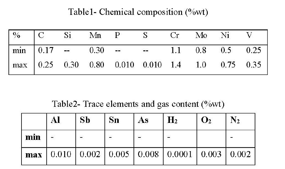
- Material for forgings shall be electric arc melted, vacuum degassed and electro slag remelted (ESR) 1.6979 steel. Chemical composition, trace elements and gas content of the alloy shall be according to tables 1 and 2.
CONDITION OF DELIVERY
- Forgings shall be supplied in hardened, tempered and rough machined as per drawing and finally stress relieved condition.
MANUFACTURE
- Forging Process
- The forgings shall receive their hot mechanical work under a press, hammer, or mill of sufficient power to work the metal throughout its section. The forging process adopted shall ensure uniform working throughout the cross section.
- To insure proper working of the metal, the forging ratio shall be minimum 4 if bars are used for forging stock in case of shaft forging. The forging ratio is the ratio of cross sectional area of ingot to that of the main body of the forging. It is important to maintain the axis of the forging same as the axis of forging stock
- For forging of discs, the forgings shall be upset by forming from a bar having an axial length before upsetting of at least two times the thickness of discs after upsetting. The axial center of the forging shall be maintained in common with the axial center of the ingot.
- The supplier shall submit the detailed manufacturing and testing plan (MTP) indicating the bar dimensions, forging process, forging ratio, heat treatment plan, sketches showing test sample locations and stages of
Gas Turbine Rotor RFP
| Document Code | Revision | Date | ISO Code | Page | |
| PENG-RFP | 02 | 2014/05/09 | 16 of 21 |
inspection etc for approval by HY before starting production. The approved MTP duly endorsed by the HYrepresentative shall be submitted along with the test certificates.Welding of forgings, including weld repair is prohibited.
- Heat Treatment
- Forgings shall be hardened and tempered so as to obtain uniform mechanical properties all over the forging. Vertical heat treatment of the shaft is recommended. Heat treatment shall consist of quenching and tempering to achieve the required mechanical properties as indicated in table. Mechanical testing shall be performed in accordance with ASTM A 370. The actual heat treatment cycles are to be selected by the manufacturer based on his experience. The detailed process plan for heat treatment of forgings shall be brought to the attention of HY prior to heat treatment.
Table 3- Tensile and Notch Toughness Requirements for 1.6979 steel (After Heat treatment & Prior to stress relief)
| Direction: | LITIQ (md1cates test piece directionLong1tudinal/Tangential/Transversal) |
| Proof Stress (MPa): | mm600 |
| Tensile Strength (MPa): | 700-850 |
| Elongation (%): | 17/15/12 |
| Red. Of Area(%): | 40/40/40 |
| Impact Value (J) | 31/24/16 |
Note:
- Maximum numbers of reheat treatments permitted are three. However, retempering is not considered as reheat treatment operation.
- Rough Machining
- The forging shall be rough machined to within 13, millimeters (1/2 in) per surface of the finished forging dimension prior to heat treatment for mechanical properties.
- Stress Relieving
- After heat treatment for final mechanical properties forgings shall be secondary rough machined completely and then stress relieved with the mechanical property test samples at a temperature of 27 to 55°C below the final tempering temperature. Forgings shall be kept at stress relief temperature for a period of 1 hour per inch of forging’s main radial thickness.
- REQUIREMENTS OF FORGINGS
- Microstructure, Inclusion Rates and Grain Size
- Microstructure of the forging shall be uniformly distributed tempered Martensite or Bainite throughout the cross section of the rotor. Free ferrite is not permitted.
Gas Turbine Rotor RFP
| Document Code | Revision | Date | ISO Code | Page | |
| PENG-RFP | 02 | 2014/05/09 | 17 of 21 |
- The inclusion rating number of the samples cut from the forging for all types A,B, C & D shall not be greaterthan 1.0 (thin series) and 1.0 (Heavy series) as per ASTM E45 method A
- The grain size of forgings shall be predominantly 5 or finer as determined by ASTM El 12
- The grain size of forgings shall be predominantly 5 or finer as determined by ASTM El 12 4-2
Ultrasonic Inspection
- Ter heat treatment and mechanical testing, all forgings shall be subjected to ultrasonic test, according to pulse echo method with 2MHz normal probe (and special probe ifrequired) over 100% of its surface. In case 100% ultrasonic test is performed prior to heat treatment (which is at the discretion of the supplier)
- Results of the same shall be compared with the results of the test conducted after the heat treatment. In case differences are found, the same shall be mentioned in the test certificates.
- AVG method shall be employed for evaluation of indications. The following indications are not acceptable;
- All individual randomly distributed indications with an equivalent flaw size greater than or equal to 2mm diameter(FBH <l. 2).
- All individual indications with a suppression of 10% or more of back wall 3- Cracks, flakes, seams and laps.
- All indications from area type of defects as well as local accumulation of indications irrespective of the size of individual indication of accumulated indications consist of.
Magnetic Particle Inspection
- The forgings shall be tested by magnetic particle test as per ASTM E 709, over 100% of its surface. Cracks and linear indications are not acceptable.
Heat stability test
- The heat stability test shall be performed on turbine rotors and shafts (if deemed necessary by the designer) after all heat treatment and rough machining processes have been finished. Procedure and acceptance criteria of heat stability test are in accordance with SEP 1950. Schematic of the test arrangement of heat stability test is shown in figure 1.


DIMENSIONS AND TOLERANCES
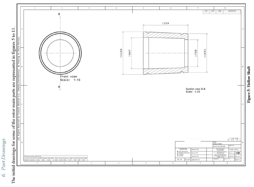
- Each forging shall conform to the dimensions and tolerances specified on the HY drawings.
CERTIFICATION AND REPORT
- Reports of all tests and inspections necessary to evaluate conformance of forgings to the requirements of this document shall be submitted. Additionally, statement of the HY engineering drawing approval and heat treat process certifications shall be submitted. Data reports shall contain the following:
- Chemical Composition and trace elements content
- Tensile and impact test report
- Microstructure, Inclusion rates and Average grain size
- Ultrasonic and Magnetic Particle Inspection
- Heat stability test report (for rotors and shafts)
Shanghai HY Industry Co.,Ltd is qualified turbine parts supplier.We have more than 15 years experience in kind of turbine parts production.
HY-industry products grad:
- inconel 600,inconel 601,inconel 625,inconel 825
- incoloy 800,incoloy 800HT,incoloy 901,incoloy 926
- monel 400,monel K500
- nimonic 901, nonomic 80A,nimonic 90
When you want to know more about our products, please contact us:
http://hynickelalloy.com/product-center/