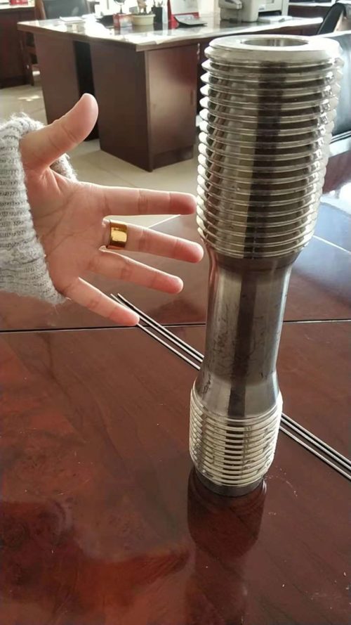
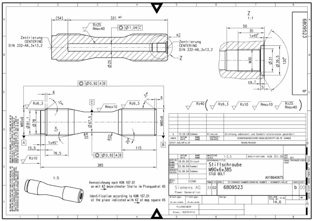
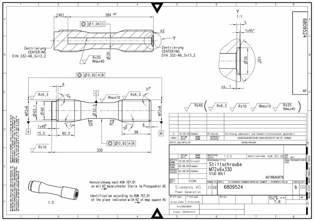
Application of HY-GH783 ( inconel783) to medium pressure valve bolts in turbine machine【Detail drawings】
Application of HY-GH783 ( inconel783 ) to medium pressure valve bolts in turbine machine.(HY-industry Technology Center)
research background
-
In recent years, with the rapid development of ultra-supercritical units, STP introduced the German Siemens technology to apply the alloy to the fastening bolts of the steam turbine intermediate pressure main valve (referred to as the middle main door) and the medium pressure regulating door (referred to as the middle adjustment door). However, in recent years, a large number of Inconel 783 bolt fractures have occurred nationwide, and the number of fractures is almost positively correlated with the fracture time. Once a medium pressure valve leaks or explodes due to bolt breakage, it will seriously threaten the safety of people and equipment.
Medium-pressure valve bolts are used as high-temperature fasteners. Generally, the fracture is closely related to the stress environment that the bolts are subjected to under different service conditions. Therefore, the main valve and door bolt system are taken as the research object, and the three-dimensional finite element stress analysis of bolts and parts (thread parts, etc.) under typical working conditions (pre-tightening, starting and stable working conditions) is carried out to explore the service life of bolts. The effect of the stress in the fracture on the fracture, and provides a useful reference for the later development of countermeasures.
1 finite element modeling
-
1.13D finite element model
The UG software is used to model the 3D overall and the mesh of the STP ultra-supercritical unit’s medium-pressure main valve and medium-pressure control door (see Figure 1), which is called the parent model. In the master model, the inconel783 (Alloy 783)bolts are temporarily replaced with polished rods, and details such as threads are ignored. In order to accurately consider the local details of the thread in the bolt during the finite element stress analysis, the bolt is further refined 3D finite element modeling (see Figure 2), which is referred to as the sub-model. In the sub-model, the thread details in the bolt are fully considered, and the mesh portion of the bolt (nut) thread portion (thread root) is locally encrypted. In the sub-model, the nut-bonnet joint surface, the bonnet-valve joint surface and the threaded teeth of the bolt and the threaded joint surface of the nut are also treated in a non-linear contact pair (take a friction coefficient of 0.2).

-
1.2 Material properties:
Figure 3 shows the variation of the elastic modulus and linear expansion coefficient of medium-pressure main valve and door bolt material (Alloy783) and valve shell and bonnet material (GX12CrMoWVNb N10-1-1) with temperature. It can be seen from Fig. 3(a) that the elastic modulus of Alloy 783 material decreases from normal temperature to 650 °C, which is relatively slow, and is maintained at about 160-180 GPa. The elastic modulus of the bonnet material is very obvious, from normal temperature. The 210 GPa dropped to around 140 GPa. It can be seen from Fig. 3(b) that due to the “Invar effect” in Alloy 783 alloy(inconel783 alloy), the coefficient of thermal expansion at room temperature is relatively low, about 9.9 x 10⁻⁶ ° C-1. As the temperature increases, the coefficient of thermal expansion of Alloy 783 alloy gradually increases, but it is still lower than the valve cover material in the range of 20-580 °C.
2. finite element stress analysis
-
The overall and local three-dimensional finite element stress analysis of medium-pressure main and medium-pressure adjusting door bolts under typical working conditions, mainly for the pre-tightening (including cold and hot tight) conditions and the maximum temperature difference between the inner and outer walls of the valve casing during the start-up period ( The following is referred to as the starting condition) and the stress analysis of the bolt and the whole part (thread part and other parts) under the maximum steam pressure occurrence time (hereinafter referred to as stable working condition). The above finite element stress analysis uses ANSYS workbench v15.0 general software, in which the inconel 783 bolt stress calculation is simulated by pre-tightening, temperature and pressure multi-field coupling.
2.1 Preload condition
-
2.1.1 Cold tight process stress analysis
The cold tightening process of the middle and middle door bolts is achieved by tightening the wrench to apply torque. Therefore, according to the relationship between the tightening torque T and the pre-tightening force F0 provided in the literature “Methods for determining the tightening torque of bolts and related discussions” (see equation (1)), the corresponding torque can be determined according to the cold tightening torque. Cold tension:

In the formula: T is the tightening torque; T1 is used to overcome the thread resistance torque of the inconel 783 thread pair; T2 is used to overcome the frictional moment between the nut and the bearing surface of the connected part (or washer); F0 is the pre-tightening force; Ng is the thread equivalent angle; ρ is the thread equivalent friction angle; d is the thread nominal diameter; d0 is the thread diameter; d2 is the thread diameter; Dw is the diameter of the nut or washer connected to the bearing plane; u is the nut and the connected piece The friction factor between the bearing surfaces; K is the tightening torque coefficient, which is 0.14 for the general machined surface (with lubrication).The cold tightening moments of the middle and middle door bolts are 1 300 Nm and 760 Nm respectively, and the corresponding preload force can be determined according to formula (1).

Under the above-mentioned cold tightening force, the maximum stress in the middle main door bolt appears at the root of the first thread (upper side) that is engaged with the nut, reaching 87.7 MPa; the maximum stress in the middle adjustment bolt appears in the lower part of the bolt and the valve casing The first root of the occlusal thread (lower side) has a stress value of approximately 112.2 MPa. In addition, the thread portion and the polished rod transition position stress are also relatively large.
2.1.2 Thermal stress stress analysis
The heat-tightening process of the main inconel 783 door bolt and the middle-adjustment door bolt during installation is achieved by measuring the bolt elongation. Among them, the elongation and deviation of the middle main door bolt after heat tightening are: ΔLM=(0.24+0.05) mm, and the elongation and deviation after the heat adjustment of the middle adjustment bolt are: ΔLM=(0.20+0.05) mm. In order to consider the influence of the deviation of the bolt heat-tightening process elongation, the bolt thermal stress analysis is mainly for the upper and lower boundaries of the bolt elongation, namely: for the middle main door bolt: ΔLM=0.24, 0.29 mm; for the middle adjustment door bolt : ΔLM = 0.20, 0.25 mm.
(1) Main door bolts.
Apply a pre-tightening force to the center main bolt. The maximum stress in the bolt appears on the first thread root (upper side) that engages the nut, as shown in Figure 4. When the pre-shrinkage of the bolt is 0.24 mm, the stress reaches 421.9 MPa; when the pre-shrinkage is 0.29 mm, the stress reaches 514.1 MPa, which is 92.2 MPa higher than the pre-tightening stress of 0.24 mm.

(2) Middle adjustment door bolts(inconel 783).
A pre-tightening force is applied to the middle adjustment bolt, and the maximum stress in the bolt appears on the first root (lower side) of the thread that engages the valve housing at the lower part of the bolt, as shown in FIG. When the bolt pre-shrinkage is 0.20 mm, the stress reaches 320.6 MPa; when the pre-shrinkage is 0.25 mm, the stress reaches 412.9 MPa, which is 92.3 MPa higher than the 0.20 mm pre-tightening stress. In addition, a large stress is also present at the upper thread of the bolt and the nut thread engagement portion of the nut. The thread portion and the polished rod transition position stress are also relatively large.

It can also be seen from Fig. 5 that even with the same thread, the stress distribution under the preload force is extremely uneven.
2.2 startup conditions
2.2.1 Stress distribution of main door bolts
Figure 6 shows the time-dependent curve of the main door reheat steam pressure (PA) and the central main valve case temperature measurement point 50% and 100% position temperature difference ΔT (100% – 50%) during start-up conditions. Since the temperature stress is the main consideration in the starting condition, the maximum temperature difference point between the inner and outer walls is used as the temperature stress calculation position. From the maximum temperature difference between the 100% measurement point and the 50% measurement point in Figure 6 (about 40 ° C), the temperature difference between the inner and outer walls of the valve casing can be estimated to be about 80 ° C, and the corresponding reheat steam pressure is 1.7 MPa.

From the stress analysis of the main door inconel 783 (UNS N07783 )bolts under the starting conditions, it can be concluded that the maximum stress in the bolts appears on the upper side of the first thread root that is engaged with the nut (see Figure 7):
(1) When the heat tightness is 0.24 mm, the maximum stress of each bolt in the middle main door varies from 533.8 to 555.5 MPa. The bolt stress under start-up conditions is greater than approximately 25% of its initial pre-tightening stress (421.9 MPa).
(2) When the heat tightness is 0.29 mm, the maximum stress of each bolt in the middle main door varies from 617.6 to 644.9 MPa. The bolt stress under start-up conditions is greater than approximately 20% of its initial pre-tightening stress (514.1 MPa).In addition, there is also a large stress in the portion of the first tooth that the lower thread of the bolt engages with the valve casing.
2.2.2 Stress distribution of middle door bolts(inconel 783)
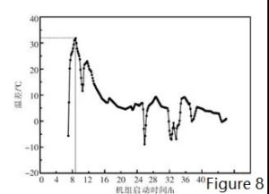
Figure 8 shows the 50% and 100% position temperature difference of the mid-valve valve case temperature measurement with time in the starting condition; the reheat steam pressure of the middle adjustment door is shown in Figure 6(a). Since the temperature stress is the main consideration factor under the starting condition, the maximum temperature difference point of the inner and outer walls is used as the temperature stress calculation position. From the maximum temperature difference between the 100% measurement point and the 50% measurement point (about 30 °C), it can be estimated that the temperature difference between the inner and outer walls of the middle adjustment valve shell is about 60 °C, and the corresponding reheat steam pressure is 1.75 MPa.
The stress analysis of the middle door inconel 783 bolt from the starting condition can be summarized as follows:
-
When the heat tightness is 0.20 mm, the maximum stress on each bolt varies from 359.4 to 374.5 MPa. The maximum stress appears on the lower side of the first thread root that meshes with the valve housing (see Figure 9), but is slightly larger than the initial pre-tightening stress of the bolt (320.6 MPa).
-
When the thermal elongation is 0.25 mm, the maximum stress on each bolt varies from 425.9 to 445.4 MPa. The maximum stress appears on the lower side of the first thread root that is engaged with the valve casing, but is slightly larger than the initial pre-tightening stress of the bolt (412.9 MPa).

2.3 stable conditions
2.3.1 Stress distribution of main inconel 783 door bolts:
Figure 10 shows the time-dependent curve of the 50% and 100% positional temperature difference between the reheat steam pressure and the central main valve housing temperature measurement point under steady conditions. Since the steam pressure is the main consideration under stable conditions, the maximum temperature difference between the 100% measurement point and the 50% measurement point of the main main valve housing obtained at the maximum reheat steam pressure of about 5.25 MPa is about 4 °C. It is estimated that the temperature difference between the inner and outer walls of the valve casing is about 8 °C.
From the stress analysis of the main door inconel 783 bolts under stable conditions, it can be concluded that the maximum stress in the bolts appears on the upper side of the first thread root that is engaged with the nut (see Figure 11):
(1) When the thermal tightness is 0.24 mm, the stress of bolts in different positions varies from 401.1 to 413.5 MPa; the maximum stress of the middle main bolt is significantly lower than the initial prestress of the bolt (421.9 MPa). The average decline is about 5%.
(2) When the thermal elongation is 0.29 mm, the stress value of the bolt at different positions varies from 471.8 to 486.6 MPa; the maximum stress of the middle main bolt is significantly lower than the initial prestress of the bolt (514.1 MPa) The average decline is about 8%.

2.3.2 Stress distribution of the middle door inconel 783 bolt:
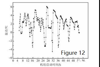
Figure 12 shows the time course of the reheat steam pressure and the mid-valve valve shell temperature measurement point (50% and 100% position) under steady conditions; the reheat steam pressure of the middle adjustment door is shown in Figure 11(a). Since the steam pressure will be the main consideration under stable conditions, the maximum temperature difference between the 100% measurement point and the 50% measurement point of the mid-valve valve shell obtained at the maximum reheat steam pressure of about 5.25 MPa is about 2 °C. From this, it is estimated that the temperature difference between the inner and outer walls of the valve casing is about 4 °C.
It can also be concluded from the stress analysis of the middle door bolt under stable conditions that the maximum stress appears on the lower side of the first thread root that engages with the valve casing:
(1) When the heat tightness is 0.20 mm, the maximum stress of each bolt is about 267 to 281 MPa. Under the steady condition, the maximum stress of the middle adjustment bolt is significantly lower than the maximum stress of the bolt under the starting condition (359-374 MPa), which is about 24% lower. It is also significantly lower than its initial preload stress value (320.6 MPa) by about 16%.
(2) When the heat tightness is 0.25 mm, the maximum stress of each inconel 783 bolt is about 326 to 327 MPa. Under the steady condition, the maximum stress of the middle adjustment bolt is significantly lower than the maximum stress of the bolt under the starting condition (426 ~ 445 MPa), which is about 24% lower. It is also significantly lower than its initial preload stress value (412.9 MPa) by about 21%.The main reason for the drop in bolt stress under stable conditions is also due to the difference in the linear expansion coefficient of the bolt material and the valve shell material and the temperature profile of the elastic modulus.
3 finite element stress analysis discussion
3.1 The effect of excessive preload on bolt breakage
The initial pre-tensioning elongation of the STP super-supercritical medium-pressure main valve bolt and the medium-pressure adjusting door bolt is set to 0.40-0.45 mm and 0.35-0.40 mm, respectively. However, too high elongation causes a large pre-tightening force, which brings a series of problems, such as the continuous interaction of local surface cracks in high stress and high temperature oxidation environment [6-7], thus promoting the easy expansion of cracks. [8], after a long time, until the crack spreads to a certain stage, a large number of Alloy783 bolts break prematurely.
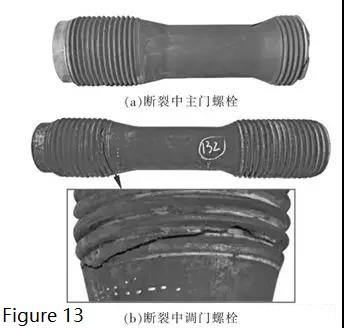
It can be seen from the broken medium pressure main steam valve and the adjusting door bolt in Fig. 13 that the bolt breaking position is basically consistent with the maximum position of the stress concentration in the finite element stress calculation result described above. Due to the large initial preload, the bolt stress is too large in various service conditions in the later stage, and high stress is a big factor for the formation of cracks, especially for SAGBO (stress-promoted grain boundary oxidation) [9-10] In other words, the high stress accelerates the damage zone formed by the grain boundary oxidation of Alloy 783 [11], which indirectly promotes the rapid development of cracks.
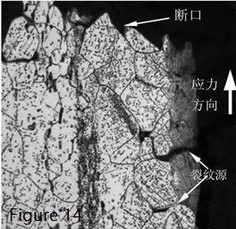
Medium-pressure valve inconel 783 bolts may cause defects (cracks, voids, etc.) on the surface due to high-temperature oxidation (corrosion) or initial processing marks on the surface, and reduce the mechanical properties of the local material [4, 12]. Larger elongation during installation further depletes the ductility of the material (or increases the brittleness of the material), thereby causing earlier cracking. The above cracks and defects (see Figure 14) will be in an open state under the action of higher tensile preload, and will continue to expand and polymerize to form macro-dominant cracks and new oxidized surfaces under high temperature alternating service environment. When the remaining bearing area of the bolt is insufficient to resist the external load, the bolt is instantaneously tensile fractured.
3.2 Down-regulation of the effect of preload
-
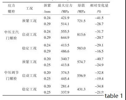
Table 1 shows the change of stress in the bolt under various typical working conditions before and after adjusting the pre-tightening force. Among them, the “original value” in Table 1 is calculated according to the same conditions as described above according to the pre-tightening force of the medium pressure main valve and the adjusting door bolt, respectively, 0.40 mm and 0.35 mm, as the downward adjustment Stress reference before preload. It can be seen from Table 1 that after the medium pressure main valve and the adjusting door bolt are lowered to 0.24/0.29 and 0.20/0.25 respectively, under the conditions of preloading condition, starting condition and stable working condition, the inconel 783 bolt is in the middle. The maximum stress has dropped significantly compared to the pre-tightening force.
-
It can also be seen from Table 1 that for the middle main door bolt and the middle adjustment door bolt, the starting condition has a large temperature difference in the valve body/outer wall, and the stress value under the working condition of the bolt is the largest among the three working conditions, so The moment when failure breaks are most likely to occur. The internal stress of the bolt in the stable working condition is the smallest among the three working conditions, and it is necessary to ensure that the valve does not leak.
-
It is worth noting that there are many comprehensive factors that cause the large-scale fracture of Alloy783 bolts, such as the corrosion resistance of the grain boundary due to the processing quality of the bolt itself [13], the surface defects of the bolt and the over-burning of the inner wall of the heating hole during installation [ 14] and other factors. Stress plays an amplifying effect among these factors, but it is not the only factor. Lowering the pre-tension elongation is mainly to reduce the amplification effect of stress on defect expansion.Based on the above analysis, it can be seen that the pre-tightening force during installation is a very large factor for the large-scale fracture of Alloy783 bolts of STP ultra-supercritical units. Under the premise of ensuring that the valve does not leak, the pre-tightening force is greatly reduced and implemented, and the large-scale bolt breakage problem can be greatly improved in a short time. From the actual service situation, the proportion of bolt breakage after the pre-tightening force is lowered is very significant.
4 Conclusion
Taking the medium-pressure valve bolt system of STP ultra-supercritical unit as the research object, the three-dimensional finite element stress analysis of the bolt and the whole part under typical working conditions is carried out. The results show that:
(1) Excessive pre-tightening force during installation is a major factor in the large-scale fracture of Alloy783 bolts of STP ultra-supercritical units.
(2) The maximum stress of the finite element calculation of the bolt under preloading, starting and stabilizing conditions is concentrated on the position of the first thread of the threaded part and the nut or the valve body; the internal stress of the bolt is the largest when the working condition is started.(3) After reducing the pre-tensioning elongation, the pre-tightening force of the medium-pressure valve bolt is also significantly reduced compared with the past, so that the proportion of short-term bolt breakage is significantly reduced.
HY-GH783/Alloy 783/ Inconel 783/ UNS R30783/
Material grades and equivalents Inconel 783 / Alloy 783 / UNS R30783 /GH 783
Short Introduction:
HY-GH783/GH6783 Similar grades:
Inconel 783 / UNS R30783 / GH783/GH6783 // Alloy 783 is a new “W” nickel-cobalt superalloy that maintains high strength and excellent corrosion resistance while maintaining a low coefficient of thermal expansion. The HY-GH783 developed by HY-industry has been widely used in medium pressure valve bolts in India, Iran, China, Middle East, Czech Republic and other countries.
HY-GH783 is an oxidation resistant low coefficient of thermal expansion (low CTE) superalloy developed for gas turbine applications.
The alloy is strengthened by a precipitation-hardening heat treatment made possible by additions of niobium and aluminum. In addition, the aluminum content provides excellent resistance to oxidation at high temperature.
The alloy’s density is 5% less than those of super alloys such as INCONEL alloy 718. The combination of low expansion, high strength and excellent resistance to oxidation makes the alloy especially useful for gas turbine and steam turbine components.
The low expansion enables closer control of clearances and tolerances for greater power output and fuel efficiency.
HY-Alloy 783 Chemical composition:
| Alloy | % | Ni | Cr | Co | Cu | Fe | Al | Si | Mn | S | P |
| Alloy 783 | Min. | 26 | 2.5 | Rest | 24 | 5.00 | |||||
| Max. | 30 | 3.5 | 0.05 | 27 | 6.00 | 0.5 | 0.5 | 0.005 | 0.015 |
HY-Alloy 783 Physical properties:
| Density | 7.7-8.03 g/cm3 |
| Melting point | 1338-1380 ℃ |
| Hardess | HB335 |
HY-Alloy 783 minimum Mechanical properties in the room temperature:
| Alloy | Tensile Strength Rm N/mm2 | Yield strength RP0.2N/mm2 | Elongation A5 % |
| Solution | 1158 | 1034 | 15 |
HY-Alloy 783 Characteristic as below:
It is a new “W” nickel-cobalt superalloy that keeps the alloy high strength and excellent corrosion resistance while having a low thermal expansion coefficient.
HY-Alloy 783 Application field:
Widely used in aviation, aerospace, petroleum, chemical, shipbuilding industry. Nickel-base superalloy occupies a particularly important position in the entire superalloy field, and it is widely used to manufacture the hottest end parts of aviation jet engines and various industrial gas turbines.

