
The engine principle that everyone can understand. (the design of stellite welding valve, shared by HY-Industry)
 About HY-Industry: With more than 20 years of senior internal combustion engine and steam turbine material suppliers, we are good at systematic introduction of principle and design experience. Concerned about HY, there will be gains!(https://hynickelalloy.com/)
1 valve working conditions
The valve is the part with the highest thermal load in the combustion chamber, especially the exhaust valve. The rod and the head are repeatedly washed by the exhaust gas. The temperature of the exhaust valve head of the gasoline engine can reach 700-780 °C. For diesel engines, the temperature of the exhaust valve head can reach 500-600 °C, which significantly reduces the high-temperature strength of the valve.
At the same time, lead and sulfur in the fuel have a strong corrosive effect on the valve, which easily causes the valve to produce pitting, and the pitting point is extended to a certain extent, which may cause the valve to ablate and be damaged. In addition, the valve is also subjected to high alternating impact loads.
2 Determination of the main size of the valve
(1) Determination of the size of the valve head
The first step in valve design is to determine the size of the valve head. The factors affecting the size of the valve head are mainly the cylinder diameter, the number of valves per cylinder, the position of the spark plug or injector, the design of the valve seat and the cylinder head combustion chamber.
(2) Valve head thickness t (see Figure 7-5)
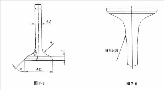
In order to ensure the stiffness of the valve head, the thickness of the valve head is generally taken from 0.08 to 0.12 Dv. If the valve head is not stiff enough, When the valve is working, the head is easily deformed, causing the sealing surface of the valve seat to wear in an arc shape, thereby aggravating the wear of the valve and the valve seat. On the other hand, the valve head is too thin, and the hard alloy layer of the tapered surface is also easily cracked due to deformation of the valve head. In order to reduce the clearance volume of the valve and the piston, the diesel engine usually has a flat bottom.
(3) Valve seat angle αConsidering the sealing wear and the reasonableness of the airflow, the right angle of the intake valve seat is 30o, and the right angle of the exhaust valve seat is 45o.
(4) Valve back cone angle βThe valve back cone angle β is usually about 20°, which can be finally determined by the airway steady flow test. The valve back cone angle has a great influence on the stiffness of the valve head. In order to ensure the stiffness of the valve head to reduce the wear of the valve and the valve seat, it is desirable to use a larger valve back cone angle, but the larger valve back cone angle will increase. The inertial mass of the atmospheric gate, so the choice of the valve back cone angle should be determined based on the airflow steady flow test, the valve head stiffness, and the valve dynamic characteristics.
(5) Transition fillet radius R of the valve head and the stem
The transition fillet radius R also has a certain influence on the flow of the airflow, but its influence on the stress distribution level of the valve head is more important. Usually, the transition fillet radius of the exhaust valve is larger than the fillet radius of the intake valve.
For the intake valve of the supercharger, a larger transition radius is adopted and the valve stem portion and the transition portion are made to have a certain taper, which can reduce the intake resistance and improve the charging efficiency.
About the exhaust valve, from the perspective of reliability, the rod and the transition fillet are tapered, see Figure 7-6. This area is often subjected to high temperature exhaust gas shocks and is very sensitive to corrosion and fatigue failure. The tapered transition can increase the life of the exhaust valve without adding a lot of valve mass.
(6) Valve stem diameter
The length of the valve stem is determined by the arrangement of the valve train. The diameter of the valve stem is related to whether the valve stem is subjected to the lateral load when the valve is opened. When the rocker is used for transmission, the lateral force is not large, and the diameter of the stem can be small; the overhead camshaft Due to the large side thrust, the rod diameter can be larger. Usually the ratio of the diameter of the intake valve head to the diameter of the rod is: 5.5 to 5.6:1. For simplicity, the intake and exhaust valve stems take the same size.
General valve stem series is: 7,8,9mm. The clearance between the valve stem and the valve guide should be determined according to the specific engine design experience and the conduit material. Usually, the clearance between the exhaust valve stem and the conduit is 0.050~0.080. The clearance between the valve stem and the conduit is 0.025 to 0.050.
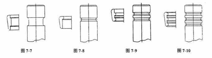
(7) Design of the lock block groove
-
Single rectangular groove design This type of lock block is designed in the United States commonly used 14 ° 15 ‘, taper lock block, so that the lock block, spring plate, valve tightly fit together. On newly developed diesel engines, this structure is basically no longer used.
-
Single arc groove design This type of construction is particularly important for small rod diameters and high stresses, with a 14° 15′ or 10° taper lock block.
-
Double arc groove design This type of lock block groove is usually used for a rod diameter of 9 mm. This arc-shaped groove is less sensitive to the notch and has a strong shear resistance, and is usually a taper of 14° 15′. The above three types of lock block design are characterized in that the lock block and the valve stem are fastened, and the valve and the lock block cannot be freely raked in the radial direction.
-
Multi-circular groove design The design feature of such a lock block is that the two lock blocks are tightened against each other instead of tightening the rod portion. Such a valve block system can freely rotate the valve by applying a lateral force to the engine running vibration or the rocker arm or the cam follower. The lock block and the groove must be quenched to obtain a certain hardness to prevent wear. This valve rotation is particularly important for reducing valve wear, but the machining accuracy of the lock block is particularly high.
3 valve material selection and processing
The intake valve is often washed by fresh air, the working temperature is not high, and the naturally aspirated engine, due to the vacuum of the intake port, the lubricating oil penetrates into the valve cone surface through the conduit to lubricate. However, for a supercharged engine, the flushing of the high temperature and high pressure dry air received by the intake valve is disadvantageous for preventing valve wear. Exhaust valves often operate at high temperatures and with corrosive gases, so materials must have high enough strength, hardness and corrosion resistance.
(1) Intake valve material
Such materials are: 40Cr, 4Cr9Si2, 4Cr10Si2Mo, the latter two materials are martensitic steels, which can increase the hardness after hardening, thereby improving the wear resistance.
(2) Exhaust valve material
The exhaust valve materials mainly include 21-4N (5Cr21Mn9Ni4N), 21-12N (2Cr21Nil2N), 21-2N, etc. These materials belong to austenitic steels, all of which are austenitic structures, so the hardness is not high. However, the material contains components such as Cr, Ni, and Mo, so the high temperature strength is high and the corrosion resistance is good. Usually, it only needs to be aging treatment, but if the high temperature strength is required, the full solid content treatment will greatly improve the fatigue strength. However, full solids processing requires strict temperature control. In addition, this material has good weldability.
(3) The following are high temperature performance comparisons of several materials
21-2N: This material is widely used in light and medium engine exhaust valves, and its price is cheaper than other materials.
21-4N: This material is also an austenitic precipitated steel of iron matrix, which is strengthened by carbon and nitrogen pore elements, and has good corrosion resistance and high temperature strength. It is better used in engines with leaded fuel.
21-12N: This material is an early developed exhaust valve material for diesel engines. This material has good oxidation resistance and The ability to vulcanize. However, due to its low metallographic porosity, the strength of the material is not very high. This material is being replaced by 21-4N.
23-8N: This material is used on lead-free gasoline and diesel engines, which have good high temperature strength and good oxidation and sulfur corrosion resistance. This material is not suitable for leaded gasoline engines.
VMS-638: This material is a low silicon alloy material that is strengthened by work hardening. This material is resistant to ablation and increases the life of the exhaust valve.
Inconel X750
For high-enhancement engines, there are some more expensive valve materials available abroad.
(4) In order to improve the wear resistance of the end of the exhaust valve stem, the following two design methods can be used:
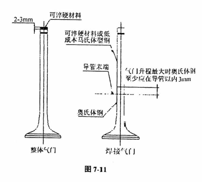
a: body austenitic steel valve :The valve rod end can be welded to harden the material (such as stellite). For example, at the valve rod end, the stellite 1 or stellite 6 is welded, and the end surface hardness is increased to 50 HRC or more, and the valve cap can be omitted.
b: welding valve :The valve stem is made of martensitic steel, and the head is made of austenitic steel. The two are combined by friction welding. This design can also reduce the cost of the valve. However, the austenitic steel at the weld at the maximum lift of the valve shall be at least 3 mm inside the conduit (see Figure 7-11).

(5) Valve cone treatment
In order to ensure reliable operation of the valve sealing cone, the Stellite series alloy is usually welded on its tapered surface to prevent pitting, corrosion and wear. There are mainly Stellite 6 and Stellite F drill-base alloy powders. Stellite 6 is commonly used for medium and heavy duty diesel engine exhaust valves; Stellite F is mainly used for exhaust valves for heavy duty gasoline engines and light diesel engines. In order to prevent the intake valve from being worn, the supercharged diesel engine usually also welds the inlet valve cone surface to the Stellite series alloy. Valve material and heat treatment are detailed in (Automotive engine valve technical conditions) GBl0483 and (Automotive Design Metal Materials Manual) GBl221.
(6) Treatment of valve stem
In order to reduce the wear of the valve stem, the valve stem must be treated:
a: pole chrome plating
In order to improve the wear resistance of the rod, chrome plating can be used, and the chrome plating should be strictly controlled in the rod inside the duct. The hard chrome deposit caused by the lock block groove and the head chrome plating is easy to reduce the fatigue strength.
Chrome standard:
Type Flash chrome plating
Thickness (mm) 7.62~20.32x 10⁻⁴
Type 3 times flash chrome plating
Thickness (mm) 0.00254~0.0508
b: rod nitriding
The nitriding treatment of the shank can also improve the wear resistance, and at the same time, the nitriding treatment at the lock block groove and the transition between the head portion and the rod portion causes the fatigue strength to decrease.
Alloy nitriding thickness (mm) :
Martensitic steel 0.0127
Austenitic steel 0.01
HY-industry is qualified Titaniumalloy,Nickelalloy&cobalt alloy materials supplier.
We have more than twenty years experience in kind of High temperature alloy production.
Inconel 718, Monel 400,stellite 6,stellite 12,stellite 1,Incoloy 800ht,Incoloy 901,Nimonic 80A,Kovar,Invar 36,Inconel 625,Hastelloy C276, Incoloy 825,6Al-2Sn-4Zr-2Mo,TI-6AL-4V ELI,TI-6AL-4V,10V-2Fe-3Al are mature productes of us.
When you want to know more about our products, please contact us:
https://hynickelalloy.com